Hydraulic fractures are created by pumping fracturing fluid into a formation at high rate and pressure. The main role of hydraulic fractures is increasing the hydraulic conductivity of the rock and facilitate the mobility of fluids during production or injection.
Applications of Hydraulic Fracturing
The most common application of hydraulic fracturing is to stimulate the reservoirs with low permeability to increase production but hydraulic fractures are also used for other purposes such as increasing injectivity for water flooding, waste disposal, in-situ thermal operations and also mitigating the formation damage caused by drilling or cementing.
While using hydraulic fracturing for enhancing hydrocarbon recovery was started several decades ago, its recent application for production from low permeability rocks through multi-stage fracking has made it the center of attention. Multi-stage fracking consists of creation of several hydraulic fractures along the horizontal section of a well.
Geometry Modeling of Hydraulic Fractures
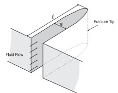
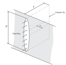
The purpose of fracture geometry modeling is finding the fracture geometry which the injected fracturing fluid occupies while accounting for the share of the leakoff fluid lost to the rock. Actual fracture geometries can be overly complex, but in their simplest form, fractures are identified as planar volumes in specific orientations. The geometries of these simple fractures are usually identified by their shape, height, length, and width.
“There are different tools for frack geometry modeling that range from simpler analytical models that assume simple geometries for a fracture to semi-analytical and numerical models that consider more complexities in the geometry of the fracture. The two models provided in this simulation, KGD and PKN, are popular analytical models that use plane-strain elastic solutions to find fracture geometry.”
Mehrdad Soltanzadeh, Industry Advisor
KGD model
This model is based on Kristianovich-Geertsma-de Klerk work who developed this analytical solution for the geometry of a hydraulic fracture. This plane-strain solution assumes a constant height for the fracture throughout its entire length. The thickness of fracture remains constant in each vertical section but it varies along the fracture. This geometry is considered more representative for the fractures that their heights are considerably more than their lengths.

PKN model
This model is based on Perkins-Kern-Nordgren work who developed this analytical solution for the geometry of a hydraulic fractures. This plane-strain solution calculates a varying height for the fracture throughout its length. The thickness of the fracture varies both in the vertical section and along the fracture length. This geometry is considered more valid if the length of the fracture is considerably more than its height.

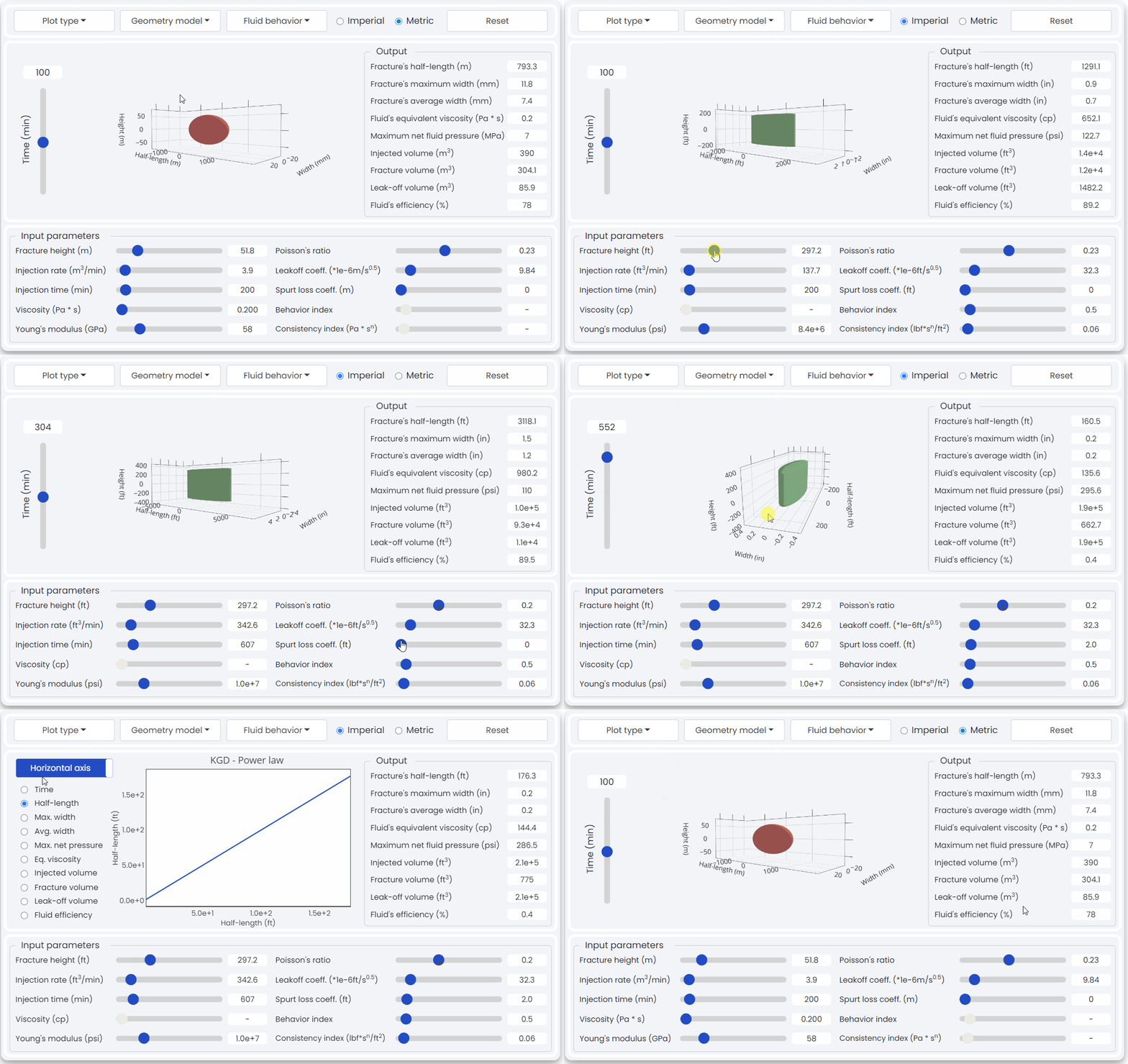
Below 👇 is the “Hydraulic Fracture Geometry Modeling” simulation hosted on the metaKinetic platform. Using this application you will be able to construct analytical models for fracture geometry using different methods with Newtonian and non-Newtonian fluids.

Want access to this simulation and more on the metaKinetic platform? Contact us!
